


Introduction
Horizontal scan-lines on camera-captured LED screens usually indicate a timing conflict between the display’s light output and the camera’s exposure.
The problem often appears after installation. The LED wall looks stable to viewers, yet recorded footage shows dark bands, rolling lines, or flicker. Buyers who specify only pixel pitch and brightness can miss this risk.
This guide explains why scan-lines appear, how refresh rate interacts with camera settings, and which LED specifications buyers should verify before placing an order.
Why Do Horizontal Scan-Lines Appear on Camera-Captured LED Screens?
Horizontal scan-lines appear when the LED display’s light-driving cycle interacts with the camera’s exposure timing. Refresh rate, PWM behavior, scan architecture, and camera settings can all influence the captured result.
An LED display does not produce light in exactly the same way that a conventional static surface appears to the human eye. The driver system controls LED output through rapid electrical cycles. Meanwhile, the camera exposes each frame for a defined period.
When these timing patterns interact poorly, the camera can record different brightness levels across parts of the display. The result can look like horizontal bands, rolling bars, or uneven brightness.
What a Camera Sees That the Human Eye Does Not
The human visual system integrates rapidly changing light over time. A camera sensor samples light according to exposure duration and frame timing. This difference explains why an LED wall can look completely stable to people while producing visible artifacts in video.
A camera-facing LED display must therefore pass a camera test, not just a visual inspection.
This distinction matters for B2B buyers. A retail display may rarely appear in professional footage, while an LED wall for broadcasting, livestreaming, events, or virtual production can remain in the camera frame for the entire production.
From a factory perspective, we evaluate the complete display configuration rather than relying on a single visual check. The LED module, driver IC, receiving card, controller, brightness setting, and camera parameters all contribute to the final result.
How LED Refresh Cycles Interact With Camera Shutter Speed
Camera shutter speed determines how long the sensor collects light for each frame. The LED system continuously updates image data and modulates LED output during that exposure period.
If the camera captures an uneven portion of the LED driving cycle, the frame can contain horizontal brightness differences. Changing shutter speed can sometimes reduce the effect because the camera samples the LED cycle differently.
However, camera adjustment should not become a substitute for proper LED system validation. If an LED wall only produces clean footage under one inconvenient camera setting, the production team may face limitations later.
For example, a broadcaster may need a specific frame rate and shutter configuration. A film crew may change camera settings during production. A livestreaming team may also use multiple cameras. The LED wall should remain compatible with the intended workflow.
The Relationship Between Refresh Rate, Frame Rate, and Exposure
Refresh rate, camera frame rate, and shutter speed describe different timing characteristics.
Refresh rate indicates how frequently the LED display updates. Frame rate indicates how frequently the camera records frames. Shutter speed determines the exposure duration of each frame.
A higher LED refresh rate can improve camera compatibility, but it does not guarantee flicker-free footage by itself.
| Factor | Effect on Camera Image | Buyer Concern |
|---|---|---|
| Refresh rate | Determines display update frequency | High |
| PWM frequency | Affects brightness modulation | High |
| Camera shutter | Controls exposure timing | High |
| Camera frame rate | Determines capture frequency | Project dependent |
| Scan mode | Affects LED driving behavior | High |
| Synchronization | Aligns display and camera timing | Critical |
A serious RFQ should therefore go beyond “3840Hz or 7680Hz.” The buyer should ask the supplier to test the complete LED configuration under the intended camera conditions.
Why an LED Screen Can Look Perfect in Person but Flicker on Camera
People and cameras do not sample light in the same way. A viewer may perceive a stable image while the camera records temporal variations within individual frames.
The problem becomes more visible when the LED wall occupies a large portion of the camera frame. A small artifact on one cabinet can become a noticeable production issue across an entire video wall.
Factory perspective: We recommend testing the display at several brightness levels because camera-facing projects often operate below maximum brightness. A configuration that looks clean at full brightness may require additional validation at lower operating levels.
Moiré Patterns vs. Horizontal Scan-Lines: Are They the Same Problem?
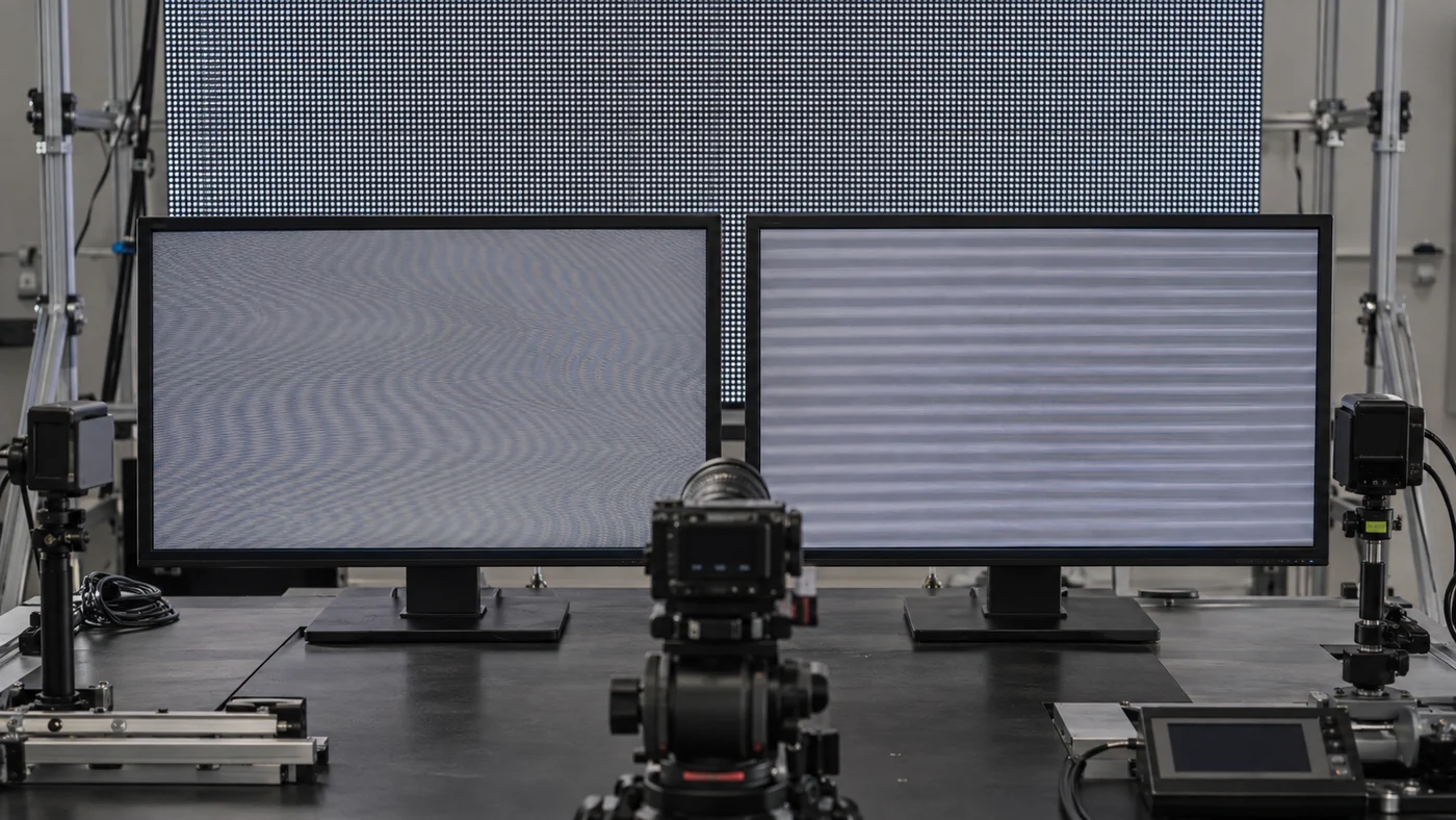
Moiré and scan-lines can appear together in LED screen footage, but they have different causes. Moiré mainly involves spatial interference between the LED pixel structure and camera sensor, while scan-lines mainly involve temporal interaction between LED driving and camera exposure.
This distinction helps buyers avoid choosing the wrong solution. Increasing refresh rate may not solve moiré, while changing camera focus will not necessarily solve persistent scan-lines.
What Causes Moiré Patterns on LED Displays
Moiré appears when the camera sensor interacts with the physical pixel structure of the LED display. The footage may show waves, ripples, repeating patterns, or color interference.
Pixel pitch can influence the visual relationship between the LED structure and camera sensor. However, pixel pitch alone does not determine whether moiré will occur.
Camera distance, focus, lens selection, sensor resolution, and shooting angle also influence the result.
What Causes Horizontal Scan-Lines
Horizontal scan-lines generally relate to temporal behavior. The LED system drives pixels while the camera captures the display during a specific exposure period.
The camera can therefore record horizontal brightness bands that move or change as the shutter setting changes.
A practical test involves changing shutter speed while keeping the camera position, focus, brightness, and frame rate controlled. If the banding changes substantially, timing interaction becomes a stronger possibility.
How Moiré and Scan-Lines Look Different in Camera Footage
Moiré normally produces spatial patterns. Scan-lines normally produce horizontal bands or rolling brightness changes.
| Issue | Primary Cause | Typical Appearance | Main Solution |
|---|---|---|---|
| Moiré | Pixel and sensor interference | Repeating or wavy patterns | Camera distance, focus, optics, LED structure |
| Scan-lines | Timing interaction | Horizontal bands or rolling lines | Refresh, PWM, synchronization, camera settings |
| Flicker | Temporal brightness variation | Brightness fluctuation | Driving system and camera timing |
Why the Two Problems Require Different Solutions
A camera operator can often reduce moiré through positioning, focus, lens choice, or shooting distance. Scan-lines may require camera timing adjustments or investigation of the LED driving system.
Factory perspective: We separate spatial artifacts from temporal artifacts before recommending a hardware change. This approach helps buyers avoid spending more on pixel pitch or refresh rate when the actual problem comes from camera configuration.
Short video placement: Insert a field-operation video here showing the same LED cabinet filmed at several shutter speeds while brightness and camera position remain unchanged.
Video purpose: Demonstrate how camera timing affects horizontal scan-lines and help viewers distinguish camera-related artifacts from persistent LED system problems.
3840Hz vs. 7680Hz: Which Refresh Rate Should You Choose?
3840Hz is sufficient for many commercial and event applications, while 7680Hz provides additional timing margin for demanding broadcast, filming, and virtual production workflows. Neither specification alone guarantees clean camera footage.
The right choice depends on the camera system, frame rate, shutter speed, brightness range, synchronization requirements, and the consequences of visible artifacts. B2B buyers should purchase the tested camera performance they need, not simply the highest refresh-rate number.
When 3840Hz Is Sufficient
A 3840Hz LED display can support many applications where cameras capture the screen, including corporate events, retail content, conferences, stage production, and many livestreaming setups.
For these projects, the buyer should still validate the actual LED configuration. The same nominal refresh rate can produce different results when the manufacturer changes the driver IC, PWM implementation, receiving card, or controller.
Factory perspective: We treat 3840Hz as a system specification rather than a standalone marketing number. During sample evaluation, we check whether the complete production configuration remains stable under the customer’s actual camera settings.
When 7680Hz Provides an Advantage
7680Hz becomes more valuable when the production environment imposes tighter requirements on camera capture.
Broadcast studios, film production, virtual production, and high-speed filming can involve specific frame rates and shutter settings that make temporal artifacts more difficult to control.
However, 7680Hz does not automatically eliminate scan-lines. If PWM behavior, scan architecture, synchronization, or camera exposure creates the artifact, simply doubling the advertised refresh rate may not solve the root cause.
3840Hz vs. 7680Hz for Events and Live Streaming
Event and livestreaming projects often need a balance between camera compatibility, system cost, and operational flexibility.
A properly tested 3840Hz configuration can be sufficient for many projects. A demanding multi-camera production may justify 7680Hz when the supplier validates the complete system.
| Application | 3840Hz | 7680Hz | Procurement Priority |
|---|---|---|---|
| Retail signage | Suitable | Optional | Medium |
| Corporate events | Suitable | Optional | High |
| Live streaming | Suitable | Recommended for demanding setups | High |
| Broadcast | Project dependent | Recommended | Very High |
| Film production | Project dependent | Recommended | Very High |
| Virtual production | Project dependent | Preferred | Very High |
| High-speed filming | Limited | Preferred | Very High |
The table should guide testing rather than replace it. If your production camera uses unusual frame rates, shutter speeds, or exposure requirements, ask the manufacturer to test those exact settings before approving the quotation.
3840Hz vs. 7680Hz for Broadcast and Studio Production
Broadcast environments require greater control because cameras can continuously capture the LED wall during live or recorded programming.
The production team may also operate several cameras with different lenses and exposure configurations. A display that works with one camera may require additional testing with another.
For broadcast projects, verified camera footage should carry more procurement weight than the refresh-rate value printed on a specification sheet.
A supplier should document the tested LED configuration and camera parameters. The buyer can then reproduce the test during sample approval.
3840Hz vs. 7680Hz for Virtual Production
Virtual production creates a particularly demanding relationship between the LED wall and camera. The display must produce stable imagery while the camera captures it under controlled production conditions.
The buyer should evaluate refresh rate together with PWM behavior, scan mode, grayscale performance, brightness, color consistency, processing, and synchronization.
We do not recommend buying 7680Hz solely because a supplier labels it as “virtual-production grade.” The specification becomes meaningful only when the complete LED configuration passes the required camera tests.
When Paying for 7680Hz May Not Solve the Actual Problem
A buyer should not immediately upgrade from 3840Hz to 7680Hz after seeing horizontal bands.
Start with controlled troubleshooting:
- Check shutter speed.
- Check camera frame rate.
- Check LED brightness.
- Verify PWM performance.
- Confirm the driver IC.
- Check scan architecture.
- Verify receiving-card settings.
- Test synchronization where applicable.
If the artifact disappears after correcting camera timing, a higher refresh rate may not provide enough additional value to justify the cost.
Why High-Refresh-Rate LED Screens Can Still Show Scan-Lines
A high refresh-rate LED screen can still show horizontal scan-lines because refresh rate represents only one part of the display’s timing system. PWM frequency, driver IC, scan mode, brightness, receiving-card settings, controller configuration, and camera exposure can all affect the captured image.
This point creates an important procurement distinction. Buyers should not diagnose every camera artifact as a “low refresh rate” problem.
Camera Shutter Speed Is Not Properly Matched
Camera shutter speed directly affects how much of the LED driving cycle the sensor captures.
When the exposure interacts poorly with the LED timing, horizontal bands may appear. The operator can often change the shutter speed and observe whether the pattern changes.
That test provides useful evidence, but it does not prove that the LED hardware has no limitations.
A professional LED supplier should identify a stable operating range rather than simply telling the customer to change the camera settings.
PWM Behavior Creates Visible Temporal Artifacts
PWM controls LED brightness through rapid switching. The camera can record this modulation differently from the human eye.
This factor becomes particularly important when the production team lowers screen brightness. A display can appear stable at maximum output but behave differently at lower brightness.
For camera-facing projects, buyers should request testing at the actual brightness range used during production.
Driver IC Performance Varies Between LED Display Configurations
The driver IC controls how LED pixels receive current and reproduce image information. Its characteristics can influence grayscale performance, current regulation, brightness control, and temporal behavior.
Buyers should therefore request the actual driver IC model rather than accepting a generic description such as “high-refresh driver.”
Factory perspective: We also consider thermal behavior during continuous operation. Different driver configurations can produce different electrical losses and operating temperatures, which can influence long-duration consistency. The correct evaluation therefore combines electrical specifications with actual module testing.
Scan Architecture Can Affect Camera Capture
Scan mode determines how the LED module distributes driving across pixel groups.
Different scan architectures can affect brightness capability, electrical loading, current distribution, and module behavior. Buyers should therefore evaluate scan mode together with pixel pitch, brightness, refresh rate, and driver IC.
A higher refresh rate does not automatically compensate for an unsuitable scan architecture.
Low-Brightness Operation Can Reveal Problems Invisible at Full Brightness
Camera production frequently requires brightness adjustment. The LED wall may run below its maximum output to match the camera exposure and surrounding lighting.
This operating condition deserves specific testing.
A useful factory test should include:
| Test Condition | What to Observe |
|---|---|
| Maximum brightness | Basic camera stability |
| Medium brightness | Temporal consistency |
| Low brightness | Flicker and scan-lines |
| Different shutter speeds | Timing sensitivity |
| Different frame rates | Capture compatibility |
| Static content | Brightness uniformity |
| Moving content | Dynamic stability |
Factory perspective: We recommend testing low-gray and low-brightness conditions because these settings can reveal issues that a bright showroom demonstration hides.
Receiving Card and Control System Settings Can Affect the Result
The receiving card processes display data before the modules reproduce it. The controller also influences how the system handles incoming signals and display timing.
A camera test should therefore use the same control hardware planned for the finished installation.
A sample cabinet with different control electronics cannot fully validate the production configuration.
What Buyers Should Check Before Blaming Refresh Rate
When scan-lines appear, use a controlled diagnostic sequence:
- Record the camera model and lens.
- Record frame rate and shutter speed.
- Record LED brightness.
- Confirm refresh rate.
- Confirm PWM specification.
- Confirm driver IC and scan mode.
- Verify receiving card and controller.
- Repeat the test using the intended production configuration.
This sequence helps the buyer identify the actual source before approving an expensive hardware change.
How to Fix Horizontal Scan-Lines Without Replacing the LED Screen
Start with camera shutter speed, frame rate, brightness, and synchronization before replacing the LED screen. If artifacts remain across reasonable camera configurations, investigate the LED driving system and production hardware.
The troubleshooting process should move from low-cost adjustments to hardware changes. This approach prevents buyers from replacing an otherwise suitable LED wall without first identifying the actual cause.
Adjust Camera Shutter Speed
Start with shutter speed because it directly controls exposure timing.
Keep other variables unchanged while testing several shutter values. Record the results so the production team can identify a stable configuration.
Adjust Camera Frame Rate
Frame rate changes the relationship between camera capture and LED refresh cycles.
The buyer should test the frame rates that the final production actually requires. A setting that works at one frame rate may not produce identical results at another.
Match Camera Settings With LED Refresh Behavior
The goal is not to find one universal camera setting. The goal is to identify a combination that remains practical for the production workflow.
Document the successful settings during sample approval so the installation team can reproduce them later.
Test Different Brightness Levels
Test the LED wall at maximum, medium, and minimum planned brightness.
This test can reveal whether the artifact appears only within a specific operating range.
Use Display-Camera Synchronization for Professional Production
Professional production environments may require synchronization between the camera and LED system.
Synchronization can reduce timing uncertainty, especially when the project uses controlled studio workflows. The exact method depends on the camera, controller, LED system, and production requirements.
When Camera Adjustments Are Only a Temporary Solution
Camera adjustments can correct a timing mismatch, but they cannot repair inconsistent LED driving behavior.
If scan-lines remain visible across practical camera settings, the buyer should investigate the LED hardware rather than forcing the production team to work around the display.
| Troubleshooting Step | Cost | Purpose |
|---|---|---|
| Adjust shutter | Low | Correct exposure timing |
| Adjust frame rate | Low | Improve capture alignment |
| Adjust brightness | Low | Check operating-range behavior |
| Change camera settings | Low | Optimize exposure |
| Synchronize systems | Medium | Improve professional capture |
| Upgrade LED configuration | High | Address hardware limitations |
Factory perspective: Before recommending a hardware upgrade, we prefer to reproduce the customer’s camera conditions on the actual LED configuration. That test gives the buyer a measurable basis for deciding whether the problem requires a new specification or simply a better system setup.
How LED Manufacturers Should Test Camera Performance Before Shipment
Buyers should test the exact production configuration with the intended camera, shutter, frame rate, brightness range, controller, and LED driving components before approving mass production.
A specification sheet can confirm that a display claims 3840Hz or 7680Hz. It cannot prove that the finished LED wall will produce clean footage under a customer’s actual camera settings.
For camera-facing projects, the acceptance standard should focus on measured camera performance rather than isolated component specifications.
Why Specification Sheets Are Not Enough
A specification sheet normally lists pixel pitch, brightness, refresh rate, cabinet dimensions, power consumption, and other technical parameters.
Those specifications help procurement teams compare products, but they do not reproduce the interaction between the LED wall and camera.
Two displays can carry the same 3840Hz rating while using different driver ICs, PWM implementations, scan architectures, receiving cards, and controllers.
Factory perspective: We recommend treating the specification sheet as the starting point of technical evaluation, not the final proof of camera compatibility.
Test the Actual Production Configuration
The factory should use the same LED module, driver IC, receiving card, controller, firmware configuration, and power architecture planned for mass production.
A demonstration cabinet can produce clean footage while the final production configuration behaves differently if the supplier changes components.
For B2B buyers, this creates an important procurement rule:
Approve the camera performance of the configuration you will actually receive, not the configuration used for a sales demonstration.
The factory should record the tested configuration so the production team can compare the final product against the approved sample.
Test Multiple Brightness Levels
A camera-facing LED display should not pass testing only at maximum brightness.
Production teams often adjust LED brightness according to studio lighting, camera exposure, content requirements, and shooting conditions.
A useful test should include several operating points.
| Brightness Condition | Main Test Objective |
|---|---|
| Maximum brightness | Basic camera stability |
| 75% brightness | Normal operating behavior |
| 50% brightness | Temporal consistency |
| 25% brightness | Low-output behavior |
| Minimum planned brightness | Flicker and scan-line risk |
Low-brightness testing matters because temporal artifacts can become more visible when the LED system operates away from its maximum output condition.
From a factory perspective, we also compare module behavior across the tested brightness range. This approach helps identify whether an issue affects one cabinet, one module group, or the complete display configuration.
Test Different Shutter Speeds and Frame Rates
The supplier should reproduce the camera parameters supplied by the buyer.
At minimum, the test should record:
- Camera frame rate
- Shutter speed
- Exposure mode
- LED brightness
- LED refresh rate
- Content type
- Camera distance
- Lens configuration
The buyer should then review the footage at normal speed and, where necessary, slow motion.
A clean image at one shutter setting does not prove universal camera compatibility.
The test should instead identify the operating range that supports the customer’s intended production workflow.
Use Slow-Motion Footage to Reveal Temporal Artifacts
Some temporal artifacts remain difficult to identify during normal-speed playback.
Slow-motion footage can expose rolling bands, brightness fluctuations, or timing patterns that disappear when viewed at normal playback speed.
The production team should compare multiple recordings rather than relying on one short clip.
This approach becomes especially useful when the LED wall will support professional filming or broadcast production.
Test the Complete System: LED Module, Driver IC, Receiving Card, and Controller
The camera sees the final optical output of the entire LED system.
The test should therefore include:
LED module → driver IC → receiving card → controller → LED wall → camera
A problem at any stage can influence the final result.
The receiving card and controller also matter because the LED module does not operate independently from the signal-processing system.
Factory perspective: We use complete-system testing because replacing only one component can change timing behavior elsewhere in the display. The final acceptance test should therefore reflect the actual bill of materials and control configuration.
Why Sample Testing Matters Before Mass Production
A production sample gives the buyer an opportunity to identify camera artifacts before the supplier manufactures the full order.
This step can reduce the risk of discovering scan-lines after installation, when replacing modules or cabinets becomes significantly more disruptive.
A practical factory validation should cover the following:
| Factory Test Item | What to Verify |
|---|---|
| Refresh rate | Configured operating value |
| PWM | Camera stability |
| Driver IC | Driving consistency |
| Brightness | Performance across operating range |
| Camera settings | Shutter and frame-rate compatibility |
| Controller | Signal stability |
| Low-gray performance | Flicker and brightness uniformity |
| Sample footage | Scan-lines and banding |
| Production BOM | Component consistency |

What Should B2B Buyers Specify in an LED Display RFQ for Camera Projects?
A camera-facing LED RFQ should specify refresh rate, PWM frequency, driver IC, scan mode, control system, brightness range, camera parameters, and required test footage.
Many buyers specify pixel pitch, cabinet size, brightness, and quantity but leave camera performance undefined. That approach creates room for different interpretations between the buyer and manufacturer.
A stronger RFQ connects the technical specification with the actual production environment.
Refresh Rate
State the minimum refresh rate required for the project.
If the application requires 3840Hz, specify it. If the project requires 7680Hz, state the reason and the intended camera conditions.
Do not write only “high refresh rate.” Give the supplier a measurable requirement.
PWM Frequency
Ask the manufacturer to provide the PWM specification alongside refresh rate.
The buyer should avoid treating these two values as interchangeable because they describe different aspects of LED operation.
Driver IC Model
Request the proposed driver IC model before approving the production configuration.
This requirement allows the technical team to evaluate the actual driving solution rather than relying on generic descriptions such as “broadcast-grade” or “camera-friendly.”
Scan Mode
Specify the required scan mode where the application makes it relevant.
The buyer should evaluate scan architecture together with pixel pitch, brightness, refresh rate, power requirements, and driver IC.
Receiving Card and Control System
The RFQ should identify the receiving card and controller used for the camera test.
If the supplier changes the control system after sample approval, the buyer should repeat the camera test.
Brightness Range
Do not specify only maximum brightness.
Instead, provide the expected operating range. A studio, livestreaming room, event stage, and outdoor advertising screen can have very different brightness requirements.
Camera Testing Requirements
Tell the supplier whether the LED wall will appear in:
- Broadcast
- Livestreaming
- Film production
- Virtual production
- Event recording
- Advertising content
The supplier can then establish a relevant test procedure.
Required Camera, Shutter, and Frame Rate
Provide the camera model whenever possible.
Also provide the planned frame rate and shutter speed. These details allow the manufacturer to test the actual interaction instead of making a general assumption.
Quick Quote Checklist
Before contacting an LED display manufacturer, provide these five parameters:
- Required refresh rate
- PWM frequency requirement
- Driver IC and scan-mode requirement
- Camera model, frame rate, and shutter speed
- Camera test and sample-footage requirement
How to Choose an LED Display for Different Camera Applications?
Camera-facing LED displays should be selected according to camera parameters, production environment, refresh and PWM performance, synchronization requirements, and acceptable image artifacts.
The procurement priority changes with the application. A retail screen occasionally captured in marketing content does not face the same technical requirements as an LED wall used continuously in a virtual-production studio.
LED Displays for Live Streaming
Livestreaming projects usually require stable footage over long operating periods.
A 3840Hz configuration can suit many livestreaming applications when the complete system passes the required camera test.
However, multi-camera productions should test each important camera configuration before mass production.
LED Displays for Broadcast Studios
Broadcast environments place greater emphasis on consistent image behavior.
The LED wall may remain visible for extended periods, and cameras may use controlled frame rates and shutter settings.
For broadcast projects, verified footage should carry more weight than the refresh-rate number alone.
LED Displays for Film Production
Film production often uses controlled camera positions and exposure settings, but crews may also use different frame rates, shutter angles, lenses, and shooting distances.
The LED supplier should reproduce the intended production conditions during acceptance testing.
LED Walls for Virtual Production
Virtual production requires close coordination between the LED wall, camera, rendering system, and production workflow.
Refresh rate matters, but it forms only one part of the evaluation.
Buyers should also examine PWM behavior, grayscale performance, brightness consistency, color reproduction, scan architecture, processing, and synchronization.
We do not recommend selecting a virtual-production LED wall based on 7680Hz alone. The complete camera-LED system should pass a controlled test first.
LED Displays for Events and Stage Production
Events often require the LED wall to work for both direct viewing and recorded content.
A properly tested 3840Hz configuration can satisfy many event applications. Projects involving demanding cameras may justify 7680Hz after validation.
LED Displays for Advertising Content Creation
Advertising agencies and brands increasingly capture LED displays as part of promotional content.
The buyer should therefore consider camera compatibility during procurement instead of testing the display only after installation.
| Application | Key Requirement | Procurement Priority |
|---|---|---|
| Live streaming | Stable camera capture | Refresh + PWM |
| Broadcast | Consistent footage | Refresh + synchronization |
| Film production | Camera compatibility | Full system testing |
| Virtual production | Camera-LED interaction | Driving + synchronization |
| Events | Reliable live capture | 3840Hz+ depending on setup |
| Content creation | Clean recorded footage | Camera testing |

The Factory Perspective: Why LED Display Performance Should Be Measured, Not Just Advertised
A camera-ready LED display should prove its performance through testing, not rely on a refresh-rate number alone.
The buyer ultimately needs clean footage, stable brightness, consistent modules, and predictable performance across the finished installation.
A specification such as 3840Hz or 7680Hz provides useful information, but the factory test determines whether the complete system satisfies the actual production requirement.
Why a Specification Number Cannot Represent the Entire Driving System
Refresh rate represents one characteristic of display operation.
It does not fully describe PWM behavior, driver IC characteristics, scan architecture, receiving-card processing, controller timing, brightness behavior, or camera synchronization.
That is why procurement teams should evaluate specifications as a system rather than as isolated numbers.
How Component Selection Can Affect Camera Performance
LED modules combine multiple electrical and optical components.
Driver IC selection, LED package characteristics, power architecture, receiving cards, and control components can influence the final display behavior.
These choices can also affect thermal conditions and long-term consistency.
Factory perspective: We evaluate component combinations during production because a component that meets a nominal specification may still behave differently when combined with another module, driver, or control configuration.
Why Mass-Production Consistency Matters More Than a Single Demo Cabinet
One successful cabinet proves only that one configuration produced an acceptable result.
A large LED wall contains many modules and cabinets. The buyer needs consistent behavior across the complete shipment.
Factory quality control should therefore verify component consistency, module performance, calibration, cabinet assembly, and final display testing.
A camera test should not end when the first sample looks good. The production process must preserve the approved configuration.
How Factory Calibration and Quality Control Affect Camera-Captured Content
Calibration helps maintain consistent brightness and color across modules.
A camera can reveal small differences across a large LED wall, particularly when the screen forms a major part of the composition.
The factory should therefore maintain controlled calibration procedures and verify finished cabinets before shipment.
What an Experienced LED Manufacturer Should Provide Before Mass Production
A professional supplier should provide more than a PDF specification sheet.
For a camera-facing project, the buyer should request:
- Technical configuration details
- Driver IC information
- Refresh and PWM specifications
- Camera test footage
- Brightness-range testing
- Sample approval
- Production configuration confirmation
- Final quality-control records
The strongest procurement process connects the RFQ, sample approval, factory testing, mass production, and final acceptance.
LED Screen Scan-Line FAQs
Why do horizontal scan-lines appear when filming an LED screen?
They appear when the LED driving cycle and camera exposure timing interact poorly. Refresh rate, PWM frequency, scan mode, brightness, synchronization, shutter speed, and frame rate can all affect the result.
Does a 7680Hz LED display always eliminate camera flicker?
No. A higher refresh rate can help, but it cannot guarantee clean footage when PWM behavior, driver ICs, scan architecture, controller settings, brightness, or camera timing remain unsuitable.
Can scan-lines be fixed without replacing the LED screen?
Often, yes. Test shutter speed, frame rate, exposure, brightness, and synchronization first. If artifacts remain across practical camera settings, test the complete LED hardware and control configuration.
Conclusion
Horizontal scan-lines on camera-captured LED screens do not automatically mean that the LED wall has an insufficient refresh rate. Refresh rate matters, but PWM, driver IC, scan architecture, brightness, control hardware, synchronization, and camera exposure determine the final result. Buyers should therefore evaluate the complete configuration before choosing between 3840Hz and 7680Hz.
Please review your current LED RFQ, add the five camera-related technical parameters, and request a camera test using your actual frame rate and shutter settings. If you are planning a camera-facing LED project, NSELED can support configuration evaluation, customized technical specifications, sample testing, and camera-performance validation so your procurement decision is based on measured application performance rather than a specification number alone.