


An LED display does not simply receive a video and “turn on” thousands of lamps. Before a visible image appears, the system must decode the source, scale it to the screen canvas, divide every frame among cabinets, convert pixel values into timed current pulses, and synchronize millions of red, green, and blue emitters.
Understanding this signal chain helps integrators diagnose failures, compare control systems, and specify a display that remains stable at the required refresh rate and brightness. This guide follows the data from the video source to the emitted light, with emphasis on the components that determine image quality and reliability.
Signal path at a glance: source device → video processor → sending controller → network links → receiving cards → hub boards and driver ICs → RGB pixels.
How Does an LED Display Process a Video Signal?
A source device produces a digital video signal, usually through HDMI, DisplayPort, SDI, DVI, or a media server output. A video processor first converts that signal into the resolution, frame rate, color format, and canvas layout required by the LED wall. The sending controller packages the processed frame into data streams and distributes them across its output ports.
Inside the wall, receiving cards read their assigned portion of the canvas. Each card forwards row, column, color, and timing data to the LED modules through a hub board or integrated interface. Driver ICs then regulate current and pulse duration for each color channel. The human eye integrates these rapid pulses into a stable full-color image.
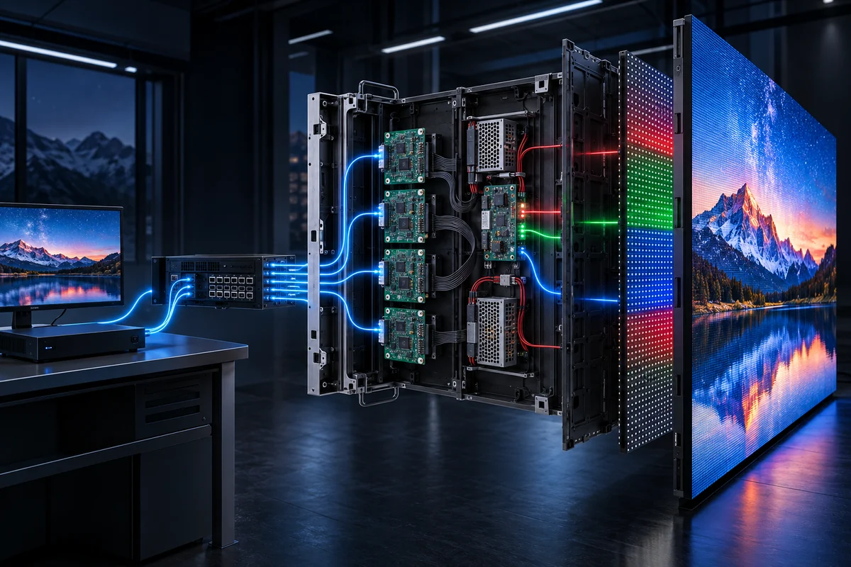
The Seven Stages Between Source and Light
1. The source creates the frame
A computer, camera system, signage player, or media server produces complete image frames. Resolution and frame rate belong to the source signal; they are not the same as LED refresh rate. A 60 fps source can be shown on a 3,840 Hz display because the screen refreshes its emitters many times during each source frame.
2. The video processor prepares the canvas
The processor scales, crops, switches, and sometimes color-corrects the input. Its output canvas must match the total mapped pixel area. If the canvas ratio does not match the physical wall, content can stretch, crop, or occupy only part of the display.
3. The sending controller packetizes pixel data
The controller converts each frame into the protocol used by the LED control system. It assigns portions of the canvas to physical Ethernet or fiber outputs. Port capacity must be calculated from pixel count, bit depth, refresh requirements, redundancy, and the controller manufacturer’s limits—not from connector count alone.
4. Network links transport the data
Copper network cables commonly connect short cabinet runs, while fiber extenders serve long distances or electrically noisy environments. The wiring order must follow the software mapping. One misplaced cable can shift several cabinets even though every cabinet still has power.
5. Receiving cards extract cabinet-level data
Each receiving card takes only the pixels assigned to its cabinet or module group. Its configuration defines module dimensions, scan mode, color order, data-group routing, and output timing. Receiving-card files are therefore product-specific; copying a configuration from a visually similar module can produce ghosting, repeated rows, wrong colors, or a black screen.
6. Driver ICs translate data into current
The module PCB routes control data to constant-current driver ICs. These devices determine which rows are active and how long each red, green, and blue channel conducts. Their current accuracy, grayscale performance, low-brightness behavior, and thermal stability directly affect uniformity.
7. RGB emitters form the visible image
Each pixel combines red, green, and blue light at controlled intensities. Nearby viewers can distinguish the individual emitters; at the intended viewing distance, the three channels blend into one perceived color. Pixel pitch sets the physical sampling density, while the controller and driver system determine how faithfully those pixels reproduce the source.
What the LED Controller Actually Controls
“Controller” is often used as a general term, but the system normally includes several functions. Separating them makes specification and troubleshooting more precise.
| Control layer | Primary job | Typical failure symptom |
|---|---|---|
| Source or media server | Generates frames and content timing | No signal, incorrect format, dropped playback frames |
| Video processor | Scaling, switching, canvas composition and input management | Cropping, wrong aspect ratio, excessive latency |
| Sending controller | Packages and distributes screen data | Entire ports or large screen areas offline |
| Receiving card | Maps data to a cabinet or module group | Repeated, displaced, discolored or blank cabinets |
| Driver IC | Controls scan timing and LED current | Ghosting, low-gray defects, lines or brightness mismatch |
For complex projects, controller selection should also consider backup inputs, port redundancy, genlock, low-latency modes, HDR processing, calibration coefficient storage, monitoring, and compatibility with the selected receiving cards.
Receiving Cards, Cabinet Mapping, and Synchronization
A receiving card is the bridge between the high-level network stream and the electrical timing required by LED modules. During configuration, software assigns a physical cabinet position to every card. The screen may be wired left-to-right, serpentine, or through multiple independent port chains, but the logical map must match the real cable route.

Synchronization matters because adjacent cabinets must display the same frame at the same instant. A mapping or timing mismatch can create horizontal tearing, offset motion, or a visible boundary during camera capture. Broadcast, virtual production, and control-room projects may additionally require a common reference clock or genlock across processors and cameras.
When commissioning, technicians should test solid colors, grids, moving diagonals, grayscale ramps, and rapid motion. These patterns reveal mapping errors that a normal promotional video can hide.
How Driver ICs Create Grayscale and Color
An LED is fundamentally current-driven. The driver IC regulates that current so pixels of the same command value produce comparable output. Color is created by adjusting the relative output of the red, green, and blue channels; grayscale is created by dividing time into controlled pulse intervals.
Pulse-width modulation
Pulse-width modulation, or PWM, switches each channel rapidly. A longer on-time produces more perceived light; a shorter on-time produces less. The switching is faster than normal visual perception, so the observer sees a steady intensity rather than individual flashes.
Bit depth and usable grayscale
A higher nominal bit depth provides more possible intensity steps, but the number on a specification sheet does not guarantee smooth low-gray performance. Driver architecture, clock design, calibration, refresh settings, and brightness reduction all affect how many levels remain visibly useful.
Constant-current accuracy
Small current differences become visible as color or brightness non-uniformity, especially at low luminance. High-quality driver ICs maintain tighter channel consistency across temperature and operating time. This is why two modules using similar LEDs can produce noticeably different images.
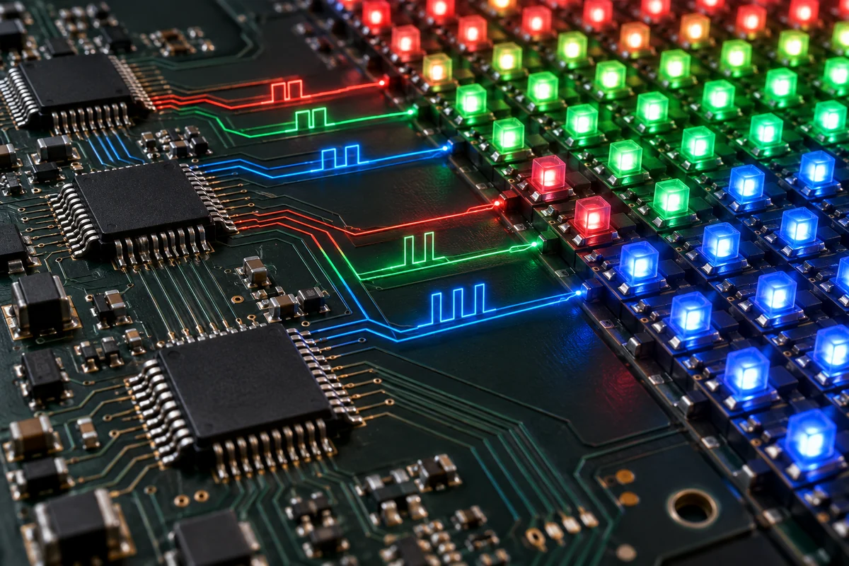
Scan Ratio: Why Rows Are Driven in Sequence
Many LED modules use multiplexed scanning instead of powering every row continuously. In a 1/16-scan design, for example, the control system activates groups of rows in a repeating sequence. Scanning reduces the number of driver channels and can improve cost and layout efficiency, but it places greater demands on timing and current control.
Scan ratio influences achievable brightness, refresh rate, power behavior, camera performance, and module design. A lower scan ratio is not automatically better, because the final result depends on the complete combination of LEDs, driver ICs, PCB layout, control parameters, and thermal limits.
Incorrect scan configuration is especially distinctive: rows may repeat, alternate, remain dark, or show unstable brightness. Technicians should load the approved receiver configuration before replacing hardware.
Refresh Rate, Frame Rate, and Shutter Interaction
Frame rate describes how often new content frames arrive. LED refresh rate describes how frequently the display completes its internal light-output cycles. They are related but not interchangeable.
A high refresh rate helps cameras capture the display without dark bands, but it is only one part of camera compatibility. Scan mode, PWM waveform, shutter speed, frame synchronization, grayscale settings, and driver IC performance also matter. Our detailed guide to 3,840 Hz versus 7,680 Hz LED refresh rates explains why a larger number alone does not guarantee a clean camera image.
If horizontal bands appear, test multiple shutter settings and inspect the system using the method in our LED screen scan-line troubleshooting guide.
Where Latency Enters the Signal Chain
Latency accumulates rather than coming from one component. Content decoding, format conversion, scaling, frame synchronization, sender buffering, receiver processing, and camera workflows can each add delay. Some processors offer low-latency or frame-lock modes, but these may limit scaling, rotation, redundancy, or advanced image correction.
| Source of delay | How to reduce it | Trade-off to verify |
|---|---|---|
| Media playback | Use hardware decoding and a stable output format | Codec and synchronization capability |
| Video processing | Avoid unnecessary conversions and enable low-latency mode | Scaling, switching and backup features |
| Frame synchronization | Use a common reference where required | Compatibility across the full signal chain |
| Controller mapping | Use efficient port loading and approved firmware | Redundancy and serviceability |
Power and Thermal Behavior Affect Signal Quality
Signal processing cannot be evaluated separately from power. A module may receive correct data but still flicker, color-shift, or restart when DC voltage drops under load. Power supplies should be sized for realistic image content, ambient temperature, derating, and circuit distribution rather than average consumption alone.
Driver IC temperature also affects output stability. Dense fine-pitch modules concentrate heat close to the LEDs and control electronics. Cabinet airflow, PCB copper, power efficiency, brightness settings, and ambient conditions determine whether the display can sustain calibrated output. For system planning, review the site’s LED display power consumption and electrical load.
Calibration Happens After the Signal Path Works
Calibration measures individual pixel output and stores correction coefficients that compensate for brightness and color variation. These coefficients are applied during signal processing before the driver commands reach the pixels.
Calibration cannot repair a defective LED, wrong scan configuration, unstable power supply, or mismapped cabinet. Hardware and configuration faults must be corrected first. It is also important to preserve factory calibration files and back them up before changing receiver parameters. See the LED screen calibration guide for measurement and acceptance details.
Engineering Checklist for a Stable Signal Chain
- Confirm the source resolution, frame rate, color depth, and connector standard.
- Calculate the canvas and load of every controller output port.
- Document the physical cable route and logical receiving-card map.
- Use the approved module and receiving-card configuration files.
- Verify driver IC model, scan ratio, refresh setting, and grayscale behavior together.
- Measure DC voltage at the farthest modules under a high-load test pattern.
- Test solid colors, grayscale ramps, grids, motion, and camera shutter interaction.
- Back up configuration and calibration files after final acceptance.
- Record firmware versions and keep known-good spare receiving cards and modules.
If the system already shows black sections, repeated cabinets, or intermittent signal loss, use the structured checks in our LED display troubleshooting and repair guide.
LED Display Signal Processing FAQs
What is the difference between an LED controller and a receiving card?
The sending controller converts processed video frames into display data and distributes them through output ports. Receiving cards inside the display extract the pixels assigned to their cabinets and generate the module-level timing and data outputs.
Does a higher LED refresh rate always produce better image quality?
No. Refresh rate helps motion and camera capture, but image quality also depends on driver ICs, scan mode, grayscale, calibration, source quality, brightness, and correct control parameters.
Why does an LED cabinet show the wrong color or repeated rows?
Common causes include an incorrect receiving-card configuration, wrong RGB order, mismatched scan mode, faulty data-group routing, or damaged hub and module connections. Load the approved configuration and verify cabling before replacing LEDs.
Can calibration fix every brightness difference?
Calibration can compensate for measurable pixel variation, but it cannot correct failed emitters, unstable voltage, overheating, incorrect current settings, or incompatible modules. Those faults require configuration or hardware correction first.
Conclusion
An LED display forms an image through a tightly synchronized chain: the processor prepares the canvas, the sending controller distributes it, receiving cards map it, driver ICs convert data into timed current, and RGB pixels emit the final light. Stable performance depends on every stage working with the correct configuration, power margin, thermal design, and timing.
For a project-specific controller map, signal architecture, or module configuration review, contact NSELED with the screen resolution, cabinet layout, input format, camera requirements, and installation distance.