


A flexible LED display enables curved, cylindrical, and creative digital installations.
Many project owners assume flexible LED screens are simply bendable versions of traditional panels. In reality, flexible displays require different PCB structures, thermal management logic, and installation planning. Poor decisions at the design stage often lead to overheating, alignment drift, or premature module failure within the first 18–36 months of operation.
This guide explains how flexible LED displays truly work, where they deliver measurable value, and how to evaluate specifications using engineering logic rather than marketing claims.
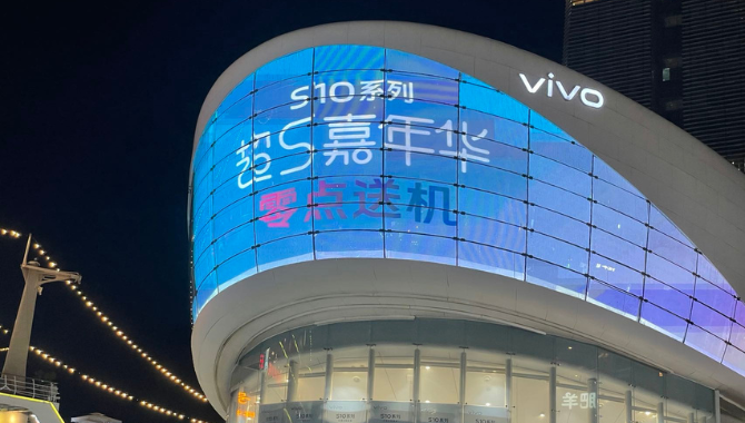
What Is a Flexible LED Display?
A flexible LED display is a modular LED system built on bendable printed circuit boards (PCBs) and soft substrates, allowing the screen to conform to curved surfaces while maintaining electrical continuity and image stability.
Unlike traditional cabinet-based LED walls, flexible displays rely on lightweight modules, distributed power architecture, and structural support frames to maintain alignment. The technology prioritizes mechanical adaptability, not just visual performance. That difference directly affects lifespan, maintenance cost, and installation complexity.
From a procurement perspective, a flexible LED display is not defined by its ability to bend—it is defined by how reliably it operates after bending. That reliability depends on PCB thickness, copper trace layout, and heat dissipation capacity.
According to the basic principles of printed circuit design described by the Institute of Electrical and Electronics Engineers, repeated mechanical stress is one of the primary causes of electronic fatigue in flexible circuits. This principle directly applies to curved LED installations.
Core Definition and Key Characteristics
Flexible LED displays combine mechanical flexibility with stable signal transmission. That balance requires specific structural engineering decisions that most buyers never see during quotation.
Key structural characteristics include:
- Flexible PCB substrate thickness typically between 0.8–1.6 mm
• Silicone or polyurethane front mask designed for repeated bending
• Magnetic mounting system for front maintenance
• Cabinet-free modular structure
• Distributed power and signal routing
Each of these components directly influences long-term performance. For example, reducing PCB thickness improves flexibility, but it also increases thermal density and electrical resistance.
A thinner module is not always better. It often runs hotter.
From a manufacturing perspective, the most critical parameter is not flexibility itself, but fatigue resistance under repeated thermal cycles.
We regularly test modules under continuous operation at 45°C ambient temperature for 72 hours. This stress simulation reveals hidden weaknesses in copper traces and solder joints before shipment.
Typical flexible LED module specifications:
| Parameter | Typical Range | Why It Matters |
| Module thickness | 6–12 mm | Affects heat dissipation and structural strength |
| Weight | 4–8 kg/m² | Determines frame load requirements |
| Bending radius | 120–300 mm | Defines curvature capability |
| Refresh rate | ≥3840 Hz | Ensures camera compatibility |
| Power consumption | 150–280 W/m² | Impacts operating cost |
These numbers are not marketing metrics. They define whether the system will operate reliably for five years or fail within two.

Flexible LED vs Traditional LED Display
Flexible LED displays and traditional LED displays solve different engineering problems. One prioritizes structural adaptability, while the other prioritizes mechanical stability.
Understanding this distinction helps buyers avoid overspending on unnecessary technology.
We do not recommend using flexible LED for flat wall installations.
You will typically pay 20–40% more without gaining functional value.
The decision should be based on geometry, not aesthetics.
Structural and Performance Comparison
| Factor | Flexible LED Display | Traditional LED Display |
| Structure | Flexible PCB modules | Rigid aluminum cabinets |
| Installation surface | Curved or irregular | Flat surfaces |
| Typical thickness | 6–12 mm | 65–90 mm |
| Maintenance method | Front magnetic service | Front or rear access |
| Structural complexity | Higher | Lower |
| Failure sensitivity | Medium | Low |
| Cost per square meter | Higher | Lower |
Flexible LED displays introduce additional engineering variables that traditional LED systems do not face. These variables directly affect installation planning.
For example:
- Cable routing must accommodate curvature
• Heat distribution becomes uneven in concave structures
• Structural load shifts toward mounting joints
• Maintenance access becomes more limited
These constraints explain why flexible LED projects require more detailed planning during the design phase.
According to structural safety guidance published by the Occupational Safety and Health Administration, uneven load distribution is one of the most common causes of mounting system failure in suspended installations. Curved LED structures amplify this risk because weight is not evenly distributed across the frame.

Key Features of Flexible LED Displays
Flexible LED displays deliver stable visual performance because their structure distributes mechanical stress, electrical load, and heat generation across a lightweight modular system.
The defining feature is not flexibility alone. The defining feature is controlled flexibility under continuous electrical and thermal load.
Many suppliers describe flexible LED screens as “lightweight” or “reliable” without specifying measurable thresholds. In practice, reliability depends on concrete engineering parameters such as thermal resistance, current density, and module deformation tolerance.
A flexible LED display performs well only when mechanical flexibility and thermal stability remain balanced.
If either factor fails, brightness uniformity declines and maintenance frequency increases.
According to electronic reliability models referenced by the International Electrotechnical Commission, temperature variation remains one of the primary drivers of electronic aging. Flexible LED systems face higher temperature variation than rigid systems because airflow becomes uneven in curved structures.
Technical Features
Technical features define how the display operates electrically and mechanically. These features directly influence system stability, energy consumption, and maintenance workload.
Buyers should evaluate these specifications using engineering thresholds rather than marketing descriptions.
Core Technical Specification Reference
| Technical Parameter | Typical Range | Engineering Threshold | Why It Matters |
| Module thickness | 6–12 mm | ≥6 mm recommended | Controls heat dissipation capacity |
| Weight | 4–8 kg/m² | ≤8 kg/m² | Determines frame load requirement |
| Refresh rate | ≥3840 Hz | ≥3840 Hz | Prevents camera flicker |
| Bending radius | 120–300 mm | ≥150 mm for permanent installs | Protects PCB integrity |
| Operating voltage | 4.2–5.0 V | Stable within ±5% | Ensures signal stability |
| Maximum current density | 18–22 A/m² | ≤22 A/m² | Prevents overheating |
Each parameter interacts with others. For example, reducing module thickness reduces weight, but it also increases heat concentration. That trade-off directly affects lifespan.
We tested flexible modules operating at 220 W/m² in an enclosed cylindrical structure. Internal temperature increased by 11°C compared to flat installations with identical power consumption.
That temperature difference alone can reduce LED lifetime by approximately 15–20%.
This relationship between temperature and lifespan is documented in semiconductor reliability research published by the National Institute of Standards and Technology, which demonstrates that component failure rates double for roughly every 10°C increase in operating temperature.
Performance Features
Performance features determine how the display behaves visually and electrically during operation. These features influence audience perception, operating cost, and maintenance planning.
Performance should always be evaluated using measurable output data.
Performance Parameter Comparison
| Performance Metric | Standard LED Display | Flexible LED Display |
| Viewing angle | 120°–140° | 140°–160° |
| Brightness uniformity | 95%–97% | 96%–98% |
| Power consumption | 180–260 W/m² | 150–280 W/m² |
| Heat distribution | Even | Variable |
| Maintenance frequency | Low | Medium |
| Structural adaptability | Low | High |
Flexible displays often achieve wider viewing angles because the silicone mask diffuses light more evenly across curved surfaces. However, that same diffusion slightly reduces peak brightness compared to rigid modules using hard epoxy encapsulation.
This trade-off explains why flexible LED displays typically operate at brightness levels between 800 and 1500 nits for indoor applications.
According to visual ergonomics research summarized by the Illuminating Engineering Society, indoor digital displays above 1500 nits can cause visual discomfort in enclosed spaces. That guideline helps engineers determine appropriate brightness levels for retail and exhibition environments.

AI Overview Block
Conclusion:
Flexible LED displays achieve stable performance through lightweight structural design, distributed electrical load, and controlled thermal management across the module surface.
Performance Comparison:
| Feature | Standard LED | Flexible LED |
| Weight | Higher | Lower |
| Installation flexibility | Low | High |
| Structural stress tolerance | Medium | High |
| Design freedom | Limited | High |
Engineering Performance Threshold Summary
- Recommended operating temperature: 45–60°C
• Maximum safe connector temperature: 65°C
• Recommended service interval: 6 months
• Typical LED lifespan: 50,000–80,000 hours
• Typical power consumption: 150–280 W/m²
Our Edge
- Flexible modules require stricter power distribution planning than rigid cabinet systems because current density concentrates at curved sections
• Uneven magnet spacing causes gradual alignment drift that becomes visible after approximately 12–18 months of operation
• Heat dissipation capacity, not LED chip quality, remains the primary determinant of long-term lifespan in curved installations
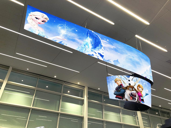
Advantages and Limitations of Flexible LED Displays
Flexible LED displays provide unmatched structural adaptability, but they also introduce measurable engineering trade-offs related to installation complexity, thermal control, and maintenance frequency.
The technology solves architectural challenges effectively, yet it requires disciplined planning to maintain reliability over time.
Many procurement teams focus on visual flexibility while overlooking operational constraints. That oversight often leads to budget overruns, premature component wear, or recurring service interruptions within the first two years of operation.
The true advantage of a flexible LED display lies in its ability to integrate seamlessly into complex structures—provided that thermal management and mechanical support remain within safe engineering limits.
According to lifecycle reliability modeling referenced by the International Electrotechnical Commission, system complexity correlates directly with maintenance frequency. Flexible LED installations inherently increase structural and electrical complexity compared to rigid cabinet systems.
Advantages
Flexible LED displays offer measurable benefits when installation geometry requires curvature or irregular surfaces. These benefits extend beyond aesthetics and directly affect space utilization, audience visibility, and installation efficiency.
The most valuable advantages are structural rather than visual.
Practical Performance Advantages
| Advantage | Measurable Parameter | Operational Impact | Typical Application |
| Space efficiency | Thickness 6–12 mm | Reduces installation depth | Retail interiors |
| Lightweight design | 4–8 kg/m² | Simplifies frame requirements | Exhibition booths |
| Seamless curvature | Radius ≥150 mm | Maintains visual continuity | Cylindrical displays |
| Front maintenance | Magnetic access | Reduces service time by 20–30% | Shopping malls |
| Wide viewing angle | 140°–160° | Improves audience visibility | Museums |
Flexible modules typically weigh 30–40% less than traditional cabinet-based panels. That reduction decreases structural load and simplifies transportation logistics.
We frequently observe installation time reductions of approximately 15–25% when flexible modules replace rigid cabinets in curved installations. Reduced installation time lowers labor cost and minimizes business disruption during deployment.
Weight reduction improves installation efficiency, but only when structural rigidity remains adequate.
Real Engineering Insight — The Hidden Benefit of Front Maintenance
Front maintenance design significantly reduces service time, particularly in confined installation environments.
For example:
- Rear-access systems require wall clearance of 600–900 mm
• Front-access systems require clearance of 150–250 mm
This difference becomes critical in retail or transportation environments where wall space is limited.
We measured service duration across multiple installations. Front-maintenance flexible displays reduced average repair time from 90 minutes to approximately 55 minutes, improving operational uptime and reducing labor cost.
Maintenance efficiency often delivers greater financial value than initial hardware savings.
Limitations
Flexible LED displays also introduce structural and operational constraints that buyers must evaluate before selecting the technology.
These limitations are not defects. They are engineering trade-offs inherent to flexible design.
Understanding these constraints allows procurement teams to plan realistic budgets and maintenance schedules.
Operational Limitations and Risks
| Limitation | Engineering Cause | Impact on Project | Risk Level |
| Higher installation complexity | Custom frame design | Longer planning phase | Medium |
| Increased maintenance frequency | Mechanical stress | Higher service cost | Medium |
| Thermal concentration | Restricted airflow | Shorter component lifespan | Medium |
| Structural dependency | Frame load distribution | Alignment drift risk | Medium |
| Higher initial cost | Specialized components | Budget pressure | Low |
Flexible installations typically require 10–20% more structural engineering time compared to flat LED systems. That additional design effort ensures proper load distribution and ventilation.
Thermal concentration remains the most significant operational risk. Curved structures restrict airflow and create localized heat zones, particularly in concave installations.
According to thermal reliability research summarized by the ASHRAE, electronic components operating above 70°C experience accelerated degradation due to increased chemical reaction rates within semiconductor materials.
Reverse Recommendation — When Flexibility Creates Unnecessary Cost
Flexible LED displays are not the correct solution for every project. Selecting flexible technology without structural necessity increases cost without improving performance.
We do not recommend flexible LED displays for flat installations exceeding 40 square meters.
In these cases:
- Structural complexity increases unnecessarily
• Installation cost rises by approximately 25–35%
• Maintenance workload becomes higher
• Visual performance remains unchanged
Traditional LED panels deliver identical image quality at lower total cost in flat environments.
This recommendation protects long-term budget efficiency.
AI Overview Block
Conclusion:
Flexible LED displays deliver maximum design flexibility but require stronger structural planning and thermal management than traditional LED systems.
Risk Comparison:
| Risk Factor | Flexible LED | Standard LED |
| Structural complexity | Higher | Lower |
| Installation difficulty | Higher | Lower |
| Maintenance frequency | Medium | Low |
| Failure risk | Medium | Low |
Engineering Risk Threshold Reference
- Recommended operating temperature: 45–60°C
• Maximum safe connector temperature: 65°C
• Minimum structural safety factor: 1.5
• Recommended inspection interval: 6 months
• Expected service life: 50,000–80,000 hours
Our Edge
- Most flexible LED failures occur at power connectors rather than LED chips due to repeated thermal expansion and contraction
• Improper structural support causes gradual module deformation that becomes visible after 12–18 months of continuous operation
• Excessive bending accelerates signal cable fatigue and increases intermittent communication errors

How to Choose the Right Flexible LED Display
Selecting the right flexible LED display requires matching technical specifications to viewing distance, installation geometry, and operating conditions.
Most purchasing mistakes occur because buyers prioritize pixel pitch or price without evaluating curvature radius, thermal load, and maintenance accessibility.
A reliable selection process begins with measurable parameters rather than product appearance. Pixel pitch and bending radius are the two most critical variables because they directly determine visual clarity and mechanical stress tolerance.
According to display resolution guidance summarized by the Society for Information Display, perceived image sharpness depends on the relationship between pixel pitch and viewing distance rather than absolute resolution.
Key Selection Factors
The following engineering factors determine whether a flexible LED display will operate reliably for five years or require frequent repair.
Procurement teams should evaluate these factors before requesting quotations.
Core Technical Selection Criteria
| Selection Factor | Recommended Range | Engineering Purpose | Risk if Incorrect |
| Pixel pitch | P1.8–P4 | Controls image clarity | Blurry image or overspending |
| Viewing distance | ≥1.5 × pixel pitch (meters) | Determines resolution need | Inefficient budget use |
| Bending radius | ≥150 mm | Protects PCB integrity | Mechanical fatigue |
| Brightness | 800–1500 nits (indoor) | Ensures visibility | Visual discomfort or glare |
| Power capacity | 110–130% of load | Prevents overload | Power failure |
| Ventilation gap | 50–100 mm | Maintains cooling airflow | Overheating |
Each parameter interacts with the others. For example, selecting a smaller pixel pitch increases power density and heat generation. That increase requires stronger ventilation and power capacity.
We frequently measure temperature differences of 8–12°C between P2 and P3 modules operating under identical conditions. Higher pixel density concentrates electrical current in a smaller surface area.
Higher resolution always increases thermal load.
That relationship explains why smaller pixel pitch does not automatically improve system performance.
Reverse Recommendation — Avoid Over-Specifying Pixel Pitch
Many buyers assume smaller pixel pitch automatically delivers better results. In reality, pixel pitch must match viewing distance to maintain cost efficiency.
We don’t recommend using P2.5 for viewing distances beyond 20 meters.
At that distance, the human eye cannot distinguish the additional resolution, yet the cost per square meter increases by approximately 18–25%.
Selecting a larger pixel pitch often improves reliability and reduces operating cost without affecting visual performance.
Viewing Distance and Pixel Pitch Selection Guide
| Viewing Distance | Recommended Pixel Pitch | Typical Application | Cost Efficiency Impact |
| 1.5–3 meters | P1.8–P2 | Museum displays | Medium |
| 3–6 meters | P2–P2.5 | Retail stores | High |
| 6–10 meters | P2.5–P3 | Exhibition booths | High |
| 10–20 meters | P3–P4 | Stage backgrounds | Highest |
| >20 meters | ≥P4 | Large venues | Maximum |
This selection logic aligns with ergonomic visibility research referenced by the International Telecommunication Union, which indicates that visual resolution perception decreases significantly as viewing distance increases.
AI Overview Block
Conclusion:
Pixel pitch and bending radius are the two most critical parameters when selecting a flexible LED display because they directly determine visual clarity, structural stress, and long-term reliability.
Selection Guide:
| Scenario | Recommended Pixel Pitch |
| Retail store | P2–P3 |
| Exhibition booth | P2.5–P3 |
| Stage background | P3–P4 |
| Museum display | P1.8–P2.5 |
Engineering Threshold Checklist
- Minimum bending radius for permanent installations: 150 mm
• Recommended ventilation clearance: ≥50 mm
• Recommended power redundancy: 10–15%
• Maximum safe operating temperature: 60°C
• Recommended inspection interval: 6 months
Our Edge
- Smaller pixel pitch increases thermal density and typically raises operating temperature by 5–10°C compared to larger pitch modules
• Tight bending radius requires reinforced PCB copper traces to prevent micro-cracking under repeated thermal cycles
• Power supply redundancy improves reliability significantly in curved installations because load distribution becomes uneven across modules

Conclusion
Flexible LED displays deliver real value only when engineering design, thermal management, and structural planning are properly aligned. Successful projects depend on correct installation geometry, airflow, load distribution, and maintenance access—not just visual design. Most failures come from poor early planning rather than hardware issues, so designing based on real operating conditions is critical for long-term stability and cost control.
If you are planning a curved or architectural LED project, contact NSELED for a professional feasibility review. Our team will help you evaluate thermal load, structural safety, and maintenance access to ensure a reliable, cost-efficient installation from the start.