


A factory acceptance test verifies that an LED video wall has been built, configured, tested, documented, and packed according to the approved project specification before it leaves the manufacturer. A useful FAT does more than confirm that the screen turns on. It checks whether the delivered system can reproduce stable images, withstand its expected operating conditions, and be installed and maintained without avoidable surprises.
This guide gives buyers, distributors, AV integrators, and project managers a practical FAT framework. It separates document review, incoming-material control, mechanical inspection, electrical testing, signal verification, image-quality testing, aging, environmental checks, spare-parts confirmation, and final release. Acceptance limits must come from the signed contract, approved drawings, product data sheet, applicable standards, and destination-market requirements. The checklist below should be adapted rather than treated as a universal tolerance specification.

What Is an LED Video Wall Factory Acceptance Test
A factory acceptance test is a witnessed or documented inspection performed before shipment. The buyer and manufacturer agree on the test scope, methods, instruments, sampling plan, acceptance criteria, responsibilities, and required evidence. Some buyers attend in person or by video; others authorize the manufacturer or an independent inspector to execute the approved protocol.
The FAT should answer four questions: Was the correct product manufactured? Does the assembled system meet the approved functional and visual requirements? Are defects recorded and corrected? Is the shipment complete, traceable, and ready for installation?
A FAT is not a substitute for site acceptance testing. Factory testing cannot fully reproduce the final structure, cable distances, power quality, ambient light, network environment, content system, or camera workflow. Site acceptance should repeat the critical checks after installation.
Define the FAT Plan Before Production
The best time to approve the FAT protocol is before mass production, not when the equipment is already packed. Early agreement prevents disputes about samples, tolerances, testing time, and rework responsibility.
- Identify the project, product series, pixel pitch, cabinet type, quantity, accessories, and software versions.
- List the approved drawings, bill of materials, data sheets, color sample, configuration files, and change orders.
- Define whether testing covers every cabinet, a statistical sample, or a complete assembled screen.
- Name the buyer, manufacturer, witness, third-party inspector, and authority permitted to accept deviations.
- Specify calibrated instruments, test patterns, operating brightness, ambient conditions, warm-up time, and test duration.
- Define pass, conditional pass, rework, retest, and rejection rules.
- Agree on the evidence package: photos, video, measurements, serial-number lists, reports, and signed records.
| FAT stage | Primary evidence | Acceptance authority |
|---|---|---|
| Pre-production review | Approved specification, drawings, BOM and test protocol | Buyer or appointed technical representative |
| In-process inspection | Material records, assembly checks and traceability | Manufacturer quality team; witness if required |
| Functional FAT | Measurements, test patterns, aging and fault records | Buyer witness and manufacturer |
| Corrective action | Nonconformance report and retest evidence | Named approver in FAT protocol |
| Shipment release | Packing list, serial numbers, final report and release note | Buyer or contract-defined authority |
Document and Configuration Review
Begin with documents because the screen can pass a visual demonstration while still containing an incorrect component, drawing revision, firmware version, or spare-parts scope. Verify that the tested product matches the commercial and engineering baseline.
- Approved cabinet and module drawings with dimensions, weight, service direction, and mounting details
- Bill of materials or approved component list for LED packages, driver ICs, power supplies, receiving cards, connectors, and cabinet materials
- Controller capacity, port loading, cable topology, redundancy design, and native canvas resolution
- Module and receiving-card configuration files, firmware versions, calibration data, and backup procedures
- Electrical diagrams, rated input, maximum and typical power conditions, protective devices, and grounding design
- Applicable declarations, test reports, labels, destination-market documents, warranty terms, and spare-parts commitments
Record every approved substitution. A functionally similar component should not be accepted automatically when the contract names a specific manufacturer or model. The change may affect heat, grayscale, efficiency, compatibility, repairability, or long-term supply.
Incoming Materials and Traceability
Traceability connects a finished cabinet to the components and production records used to build it. It becomes particularly important when buyers need matched replacement modules or when a defect appears after shipment.
| Inspection item | What to verify | Required record |
|---|---|---|
| LED packages | Approved manufacturer, package type, color and brightness bin where specified | Lot or batch identification |
| Driver ICs | Approved model and revision | Supplier and incoming-inspection record |
| Power supplies | Model, rating, certification and connector layout | Serial or batch list |
| Receiving cards | Model, firmware and compatibility | Configuration and firmware record |
| PCBs and modules | Revision, solder-mask condition and dimensional consistency | Production lot and inspection result |
| Cabinets and hardware | Material, finish, dimensions, locks and service features | Drawing revision and incoming result |
The manufacturer should isolate damaged, mixed, or unapproved materials before assembly. If multiple LED batches are allowed, the plan should define how the factory prevents visible color or brightness differences across the final screen.
Module and PCB Quality Inspection
The module inspection should combine visual examination, electrical checks, functional patterns, and documented sampling. A simple illuminated image may hide solder defects, intermittent connectors, damaged masks, weak LEDs, or low-gray abnormalities.
Visual and Assembly Checks
- PCB is clean, flat, undamaged, and uses the approved revision.
- LED packages are aligned consistently without missing, tilted, contaminated, or physically damaged devices.
- Solder joints show no visible bridging, insufficient solder, lifted pads, or unapproved repair residue.
- Masks, coatings, module frames, connectors, magnets, screws, gaskets, and cable interfaces are correctly installed.
- Module dimensions and mounting points support cabinet alignment without forcing or distortion.
Electrical and Pixel Checks
- Verify input polarity, rated voltage, current behavior, and connector integrity.
- Display red, green, blue, white, black, and selected gray levels to identify dead, stuck, weak, or color-shifted pixels.
- Test data groups, scan rows, color order, driver configuration, and low-gray performance.
- Record the pixel-defect acceptance rule stated in the contract and the method used to count defects.
- Retest repaired modules under the same conditions and maintain repair traceability.
Cabinet Mechanical Inspection
Mechanical accuracy affects installation speed, screen flatness, module interchangeability, seam visibility, and long-term service. Inspect individual cabinets and an assembled sample rather than relying only on component drawings.
| Check | Method | Acceptance basis |
|---|---|---|
| Cabinet dimensions | Calibrated dimensional measurement at defined points | Approved drawing and contract tolerance |
| Flatness and squareness | Flat reference, gauges, or approved measurement method | Project specification |
| Locks and locating pins | Repeated assembly and release test | Smooth operation without excessive force or play |
| Module fit | Install and remove modules in representative positions | No interference, unsafe gaps, or forced alignment |
| Seams in assembled wall | Display grid and solid-color patterns; inspect from defined distance | Approved visual and mechanical criteria |
| Service access | Demonstrate front or rear removal of defined components | Approved maintenance method and safe access |
For rental products, repeat connection and lock operations to confirm that handling does not create alignment problems. For fixed installations, verify mounting interfaces, structural connection points, lifting features, and service clearances against the approved installation design.
Electrical Safety and Power Testing

Electrical inspection should follow the applicable product, project, and destination-market requirements. The FAT team should not invent pass limits during testing. Use approved procedures and qualified personnel for protective-earth, insulation, leakage, dielectric, or other safety-related measurements.
- Confirm input voltage range, phase arrangement, circuit distribution, breakers, fuses, connectors, cable size, labeling, and grounding points.
- Measure representative DC output voltages at power supplies and at electrically distant modules under defined load.
- Operate high-load test patterns to identify voltage drop, overheating, resets, flicker, or connector instability.
- Verify maximum and typical power using documented brightness, content, and measurement conditions.
- Test power-up, shutdown, emergency isolation, and recovery behavior.
- If redundancy is specified, remove the primary feed or component and confirm the expected transfer behavior.
| Power test | Recorded condition | Evidence |
|---|---|---|
| Input and branch load | Supply voltage, brightness, pattern and cabinet quantity | Measured current and power |
| DC voltage distribution | Measurement points and test pattern | Voltage at source and farthest load |
| Thermal observation | Ambient temperature, duration and brightness | Power-supply, connector and cabinet temperatures |
| Restart test | Shutdown time and restoration sequence | Stable recovery without lost configuration |
| Redundancy test | Failure intentionally introduced | Transfer result and alarm behavior |
Control System Signal and Redundancy Testing
A complete signal test confirms that the processor, sending controller, receiving cards, mapping, firmware, cables, and modules operate as one system. Use the project canvas and port-loading plan rather than a small demonstration configuration.
- Verify every input and output format required by the project, including resolution, frame rate, color format, and connector type.
- Load the approved screen configuration and confirm cabinet order, orientation, rotation, and data-group mapping.
- Test port capacity, long cable runs or fiber links, backup paths, source switching, genlock, and low-latency modes where specified.
- Disconnect representative data links and receiving cards to confirm fault boundaries, alarms, and recovery.
- Back up processor, sender, receiver, mapping, and calibration files under controlled filenames.
- Record firmware versions and prevent unapproved automatic updates before shipment.
Image Quality Calibration and Camera Tests
Image-quality acceptance needs defined viewing conditions. Record the observer position, ambient light, operating brightness, warm-up time, input signal, and test pattern. Otherwise, photographs and subjective comments are difficult to compare.
| Test pattern or measurement | Purpose | Typical acceptance source |
|---|---|---|
| Full red, green, blue, white and black | Pixel defects, contamination, leakage and gross uniformity | Contract and approved defect criteria |
| Grayscale ramp and low-gray video | Banding, color shift, ghosting and driver performance | Approved sample and project requirement |
| Grid, crosshatch and fine text | Mapping, geometry, cabinet alignment and resolution | Approved drawings and native canvas |
| Moving diagonals and fast motion | Processing, tearing, synchronization and motion artifacts | Project content and processor specification |
| Brightness and chromaticity measurements | Uniformity, white point and calibration result | Signed image-quality specification |
| Camera shutter sweep | Scan lines, flicker, rolling bands and refresh interaction | Broadcast or event camera requirement |
Calibration should occur after hardware, configuration, power, and thermal issues are corrected. Keep the pre-calibration and post-calibration records when the contract requires evidence of improvement. Export the final coefficients and verify that they remain active after a controlled restart.
Aging and Thermal Stability Test
Aging testing helps reveal early failures, intermittent connections, thermal instability, and configuration loss. The protocol should define duration, test patterns, brightness, ambient conditions, monitoring interval, and what happens after a failure. The number of hours alone does not describe test quality.
- Cycle solid colors, grayscale, motion, black-to-white transitions, and representative project content.
- Monitor cabinet, power-supply, driver, connector, and exhaust temperatures at defined locations.
- Record resets, data loss, flicker, pixel failures, abnormal noise, odor, discoloration, and protective-device operation.
- Confirm stable brightness, color, mapping, and calibration after the test period.
- Document all repairs made during aging and repeat enough testing to show that the corrective action was effective.
Thermal measurements should be interpreted against the approved design and component limits. A single surface temperature does not prove that every internal component operates safely, so measurement points and load conditions must be consistent.
Environmental and Protection Tests
Environmental testing depends on product type and contract scope. Outdoor and harsh-environment displays may require water-ingress, dust, corrosion, ultraviolet, vibration, high-temperature, low-temperature, humidity, or transport testing. These tests should follow the agreed method and should not be improvised on finished customer equipment.
- Confirm enclosure, module, door, connector, gasket, drain, vent, and cable-entry construction against drawings.
- Verify the claimed IP test report or conduct the agreed witnessed test using the specified setup.
- Inspect for water paths, trapped moisture, gasket damage, corrosion risks, and incorrect fasteners after testing.
- Operate representative equipment after environmental exposure and repeat functional and insulation checks where required.
- For rental systems, confirm packaging and cabinet protection through the agreed handling or transport test.
Nonconformance Corrective Action and Retest
Every failed item should receive a unique nonconformance record. The record should identify the serial number or lot, requirement, observed result, immediate containment, root cause where required, corrective action, responsible person, retest method, and closure approval.
Do not close a failure only because the visible symptom disappeared. For repeated pixel faults, overheating, resets, or color inconsistency, determine whether the issue affects one unit, one production lot, or the complete design. The buyer should approve any concession that changes a contractual requirement.
| Disposition | Meaning | Required next step |
|---|---|---|
| Rework | Bring the item fully into compliance using an approved process | Repeat affected inspections and record repair |
| Replace | Substitute a compliant component or assembly | Verify traceability, compatibility and retest |
| Use as is | Accept a documented deviation without rework | Written approval by authorized buyer representative |
| Reject | Remove the item or lot from the project | Segregate and replace before release |
| Conditional release | Shipment allowed with defined outstanding action | Owner, deadline, site plan and formal approval |
Packing Spare Parts and Shipment Release
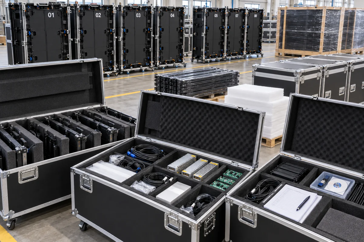
The final FAT step confirms that the tested configuration is the configuration being shipped. Verify quantities and serial numbers after repacking, especially when cabinets were moved between aging, calibration, demonstration, and packing areas.
- Cabinet, module, controller, processor, cable, structure, accessory, and tool quantities match the approved packing list.
- Spare LED modules match the approved product and are protected, labeled, and traceable.
- Spare power supplies and receiving cards include the required configuration or instructions.
- Flight cases, cartons, moisture protection, foam, stacking limits, lifting labels, and shock protection match the transport plan.
- Configuration files, calibration files, drawings, manuals, warranties, test reports, certificates, and serial-number lists are included in the handover package.
- Photographs record packed contents and case identification before sealing.
Buyer Witness Checklist
| Witness item | Pass evidence | Status |
|---|---|---|
| Approved configuration matches production | BOM, drawings, firmware and change log reviewed | Pass / Fail / N/A |
| Representative wall assembled | Cabinet order, seams, locks and service demonstrated | Pass / Fail / N/A |
| Power tests completed | Measurements and safety records attached | Pass / Fail / N/A |
| Signal and redundancy verified | Inputs, mapping, backup and recovery demonstrated | Pass / Fail / N/A |
| Image quality accepted | Patterns, measurements, calibration and camera checks recorded | Pass / Fail / N/A |
| Aging and thermal results accepted | Duration, conditions, incidents and retest evidence attached | Pass / Fail / N/A |
| Environmental evidence accepted | Reports or witnessed results match contract | Pass / Fail / N/A |
| Nonconformances closed | Authorized closure or concession attached | Pass / Fail / N/A |
| Packing and documents complete | Serial list, files, spares and packing photos verified | Pass / Fail / N/A |
| Shipment release signed | Named buyer and manufacturer representatives approve release | Pass / Fail / N/A |
LED Video Wall FAT Frequently Asked Questions
Should every LED cabinet be tested before shipment
Functional power-on and basic visual checks are normally appropriate for every cabinet, while some detailed measurements may use an approved sampling plan. The contract and risk level should define which tests require 100% inspection.
How long should an LED video wall aging test run
There is no universal duration that fits every project. The FAT protocol should define the duration together with brightness, patterns, ambient conditions, monitoring, failure response, and retest requirements. Test quality matters as much as elapsed time.
Can remote video replace an in-person FAT
Remote witnessing can be effective when the camera view, measurement instruments, serial numbers, test sequence, raw evidence, and authority to request repeat tests are agreed in advance. Critical projects may still justify an on-site buyer or independent inspector.
What happens if the screen passes FAT but fails after installation
Site conditions can introduce structural, electrical, signal, environmental, or configuration problems that were absent at the factory. Site acceptance testing should repeat critical functions and document whether the cause belongs to manufacturing, logistics, installation, integration, or operation.
Who should sign the FAT report
The report should be signed by the manufacturer representative and the buyer or authorized technical representative named in the contract. Any deviations, open actions, and conditional approvals should be listed explicitly.
Conclusion
A strong LED video wall FAT converts a sales specification into verifiable evidence. It confirms the approved components, mechanical assembly, electrical behavior, signal configuration, image quality, thermal stability, environmental protection, spare-parts scope, and shipment records before the equipment leaves the factory.
The most useful FAT is planned before production, uses project-specific acceptance criteria, records failures transparently, and requires retesting after corrective action. It reduces installation risk without pretending to replace site acceptance. Buyers should preserve the signed report, serial-number list, configuration backups, calibration files, and nonconformance records for commissioning and future maintenance.
For a project-specific FAT protocol, provide NSELED with the approved product specification, screen layout, destination market, operating environment, camera requirements, redundancy expectations, and witness arrangements before production begins.